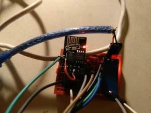

In this position capacitor C1 is charged to a positive voltage through resistor R1 and that positive voltage is seen at the RESET pin of the ESP-01 Wi-Fi module as a logic 1 (high) signal. Let’s assume the switch S1 is in the Normally Closed (N.C.) position. How the Reset Circuit Works: Refer to the sending unit wiring diagram. The solution involved using RC (Resistor, Capacitor) networks and a SPDT switch with both a Normally Open (N.O.) and Normally Closed (N.C.) set of contacts to create a reset pulse any time the switch changed state. To wake the module up from deep sleep mode required applying a (logic) high-to-low-to-high pulse to the RESET pin of the module. However, a unique challenge was encountered having to do with waking the module up when the door position switch was opened or closed.
#Esp01 deep sleep code#
Putting the ESP-01 module in its low power deep sleep mode is fairly simple and only requires a few lines of code in the software. The intent of this Instructable is to provide a design solution that solves this problem by using passive components that draw very little current when the switch is inactive regardless of its state. transistors) to generate the wake-up signal and that additional circuitry continued to drain significant battery power even though the ESP-01 module was in deep sleep. Since the garage door isn’t opened/closed that often, putting the module to sleep when not in use makes the circuit ideal for being powered by batteries.ĭuring my research in developing a design approach I found that although there are a number of published designs that use the ESP-01 deep sleep mode, they (1) only provided a wake-up signal when the switch was opened or closed but not both, or (2) required additional active circuitry (i.e. I decided to utilize the ESP8266 ESP-01 Wi-Fi module because of its low cost and its ability to go into a low power (battery saver) deep sleep mode when not in use.


#Esp01 deep sleep install#
Since there was no economical way to install new wiring in the house, the sensor had to be wireless and battery operated which in turn meant it had to use very little power. I decided to make this project because there have been a few instances where I forgot I had left the garage door open when turning in for the night. But, how do i know how long it takes to read the sensors? I don't want to set this value too low as it might switch off before the sensors are read and the data sent to the MQTT server.This project is a wireless approach to sensing the open/closed position of my garage door and displaying the door state via an LED indicator in a different location of the house. On the main config screen shown below I am unsure what to set the "Sleep awake time" to? I am guessing that this means how long it stays awake before going back to sleep. What I am aiming to do is for it to wake up every minute, check the sensor readings, and send the data to my MQTT server. I am tempted to just make some "guesses" at the right configuration but scared it might never wake up!
#Esp01 deep sleep how to#
I am confused on how to configure the deep-sleep functionality as the Wiki instructions don't reflect what I am seeing in ESP-Easy. I have followed the instructions on this page to enable deep-sleep: All the data i need is being sent back to my MQTT server. It's based on an ESP-01 and uses a BME280 and a BH1750. I have built my first project, a weather station, and I want to convert it to battery power.


 0 kommentar(er)
